To scan the cavity and display quickly the circulating power, there are 2 dedicated functions optimised for speed and convenience:C1 = Cavity_Scan(C1);
Display_Scan(C1);
However one may want to also record the reflected power. One way to do that would be to scan the cavity manually setting a different round trip phase for each iteration. Concretely, once the cavity C1 is defined it looks like:
C1 = Cavity1(IM,EM,1000,E_input); % the cavity is misaligned and not well matched to the input beam
C1 = Cavity_Resonance_Phase(C1); % will be overwritten later
Nb_point = 400; % Number of points for the scan
Phase_scan = zeros(Nb_point,1);
Power_transmitted = zeros(Nb_point,1);
Power_reflected = zeros(Nb_point,1);
for ii=1:Nb_point
Phase_scan(ii) = ii*(2*pi)/Nb_point; % Scan the round trip phase shift from 0 to 2 pi
C1.Resonance_phase = exp(1i*Phase_scan(ii)); % Set the round trip phase shift for the cavity
C1 = Calculate_Fields_AC(C1,'accuracy',1E-5);
Power_transmitted(ii) = Calculate_Power(C1.Field_trans); % store the transmitted power
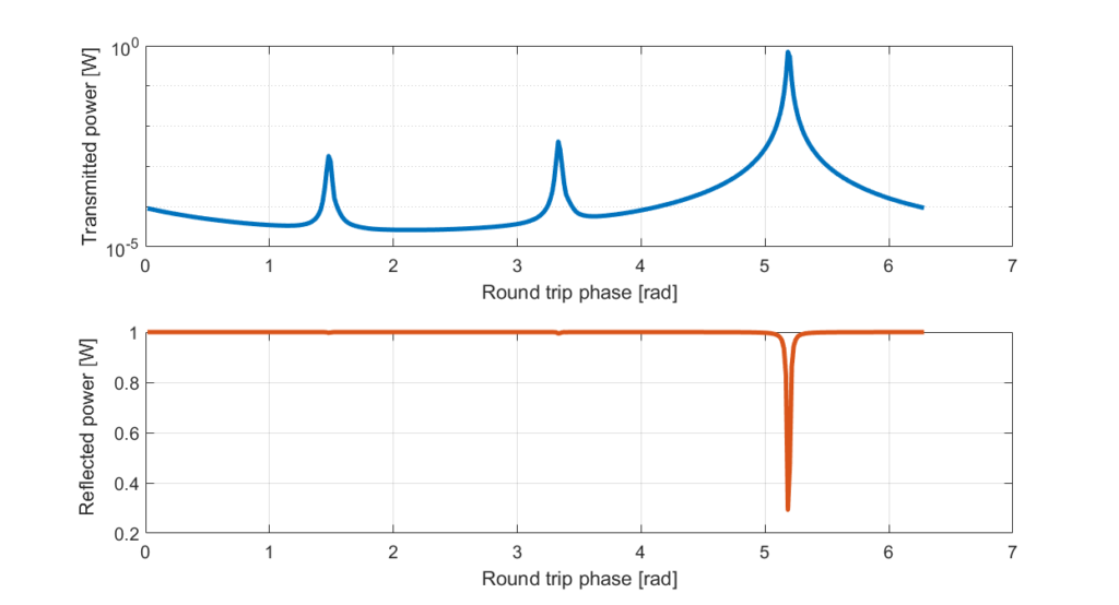
Power_reflected(ii) = Calculate_Power(C1.Field_ref); % and also the reflected one
endAnd we can then plot the transmitted power (top plot) and the reflected power (bottom one):
The technique presented here could also be used to only display a certain sideband during a scan (or an arbitrary sum of sidebands).