
In a perfectly aligned and matched Fabry-Perot cavity, one of the zero-crossings of an RF-demodulated error signal such as the PDH error signal corresponds to the cavity resonance peak. When imperfections are added, the two working points (peak resonance and zero-crossing of the error signal) can diverge.
In this example we show how, a progressive introduction of misalignment on one of the cavity mirrors, introduces a difference in the working points.
The FP cavity model is defined as follow (taken from example 3) , with a readout photodiode in reflection and a DC photodiode in transmission
model = finesse.Model()
model.parse(f"""
l l1 P=1                           # input laser
mod eom 10M 0.1 order=1            # phase modulator

# The cavity
m ITM R=0.999 T=0.001 Rc=-2500       # input test mass
m ETM R=0.999 T=0.001 Rc=2500        # end test mass

link(l1, eom, ITM, 3e3, ETM)       # linking all the components

cav cav ITM.p2.o
modes(odd, maxtem=5)

# dofs and locks
dof ITM_z ITM.dofs.z +1
lock pdh_lock pdh_err.outputs.I ITM_z.DC 0 1e-8

# Detectors - pdh readout
readout_rf pdh_err ITM.p1.o f=eom.f phase=0 output_detectors=true
pd tra_dc ETM.p2.o                 # transmitted dc power
""")
The PDH error signal demodulation phase and the lock gain are then optimized and the wp is found for the aligned version
# tuning the demodulation phase to maximize the response of the readout function
model.run(
fac.OptimiseRFReadoutPhaseDC(
"ITM_z", "pdh_err",
d_dof=1e-7)
)
# All of the following steps are taken to ultimately execute the lock command and zero the error signal
# computing the gain of the PDH signal as the DC value of the TF from ITM motion to the PDH response
sol = model.run(
fac.FrequencyResponse(
f = np.geomspace(1e-2, 1, 15),
inputs=('ITM_z'),
outputs=('pdh_err.I')
)
)
# optimizing the gain of the lock
pdh_gain = np.abs(sol['ITM_z', 'pdh_err.I'][0]) # gain of the PDH signal in W/m
lock_gain = -1/pdh_gain # optimal gain for the lock
lock_gain *= 2 * np.pi / model.lambda0 * np.rad2deg(1) # scaling the gain from m/W to deg/W
model.pdh_lock.gain = lock_gain
# running the locks
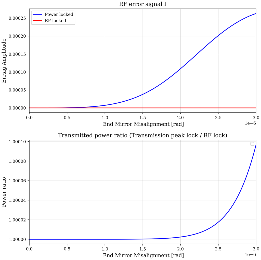
model.run(fac.RunLocks(method='newton'))Finally, we run two xaxis in parallel, introducing a progressive misalignment on one mirror, up to 3 urad. In one xaxis we are keeping the system ‘locked’ to the maximum of the transmission peak, in the second one we instead lock on the PDH error signal.
model2 = model.deepcopy()
sol2 = model2.run(
        fac.parallel.Parallel(
         fac.Xaxis(
             model.ETM.xbeta,
             'lin',
             start = 0,
             stop = 3e-6,
             steps = 100,
             #pre_step = fac.RunLocks(method='newton')
             pre_step = fac.Maximize('tra_dc', model.ETM.phi, tol=1e-20)),
        fac.Xaxis(
             model.ETM.xbeta,
             'lin',
             start = 0,
             stop = 3e-6,
             steps = 100,
             pre_step = fac.RunLocks(method='newton'))
) )
The result below show that indeed, in the top figure only one lock (the rf lock) keeps the error signal at zero, and the larger the misalignment is, the larger is the difference between the working points. The bottom figure shows that there is also (as expected) a small difference in the transmitted powers between the two working points.
# Code used for the plot:
fig, ax = plt.subplots(2,1, figsize=(8, 8))
ax[0].plot(sol2.children[0].x[0], sol2.children[0]['pdh_err_I'], label = 'Power locked')
ax[0].plot(sol2.children[1].x[0], sol2.children[1]['pdh_err_I'], label = 'RF locked')

ax[0].set_title('RF error signal I')
ax[0].set_ylabel('Errsig Amplitude')


ax[1].plot(sol2.children[0].x[0], sol2.children[0]['tra_dc']/sol2.children[1]['tra_dc'])
#ax[1].semilogy(sol2.children[1].x[0], sol2.children[1]['tra_dc'], label = 'RF locked', linestyle='--')

ax[1].set_title('Transmitted power ratio (Transmission peak lock / RF lock)')
ax[1].set_ylabel('Power ratio')

for a in ax:
    a.legend()
    a.set_xlabel(' End Mirror Misalignment [rad]')

fig.tight_layout()